ArchEngine Pre-Development Studio
1Configure
2Generate
3Proposal
Engine Online
TL
New Pre-Development Study

Turn a sketch into a
schematic proposal.

Upload a hand sketch or CAD export, set the zoning envelope and program brief, and ArchEngine will parse, audit and render a full presentation deck — end to end, in minutes.

01 · Drawing Ingestion Awaiting input
Drop a sketch, CAD file or site photo
or click to browse your device
.DWG · .DXF · .PDF · .PNG · .JPG — up to 25MB
or use reference data
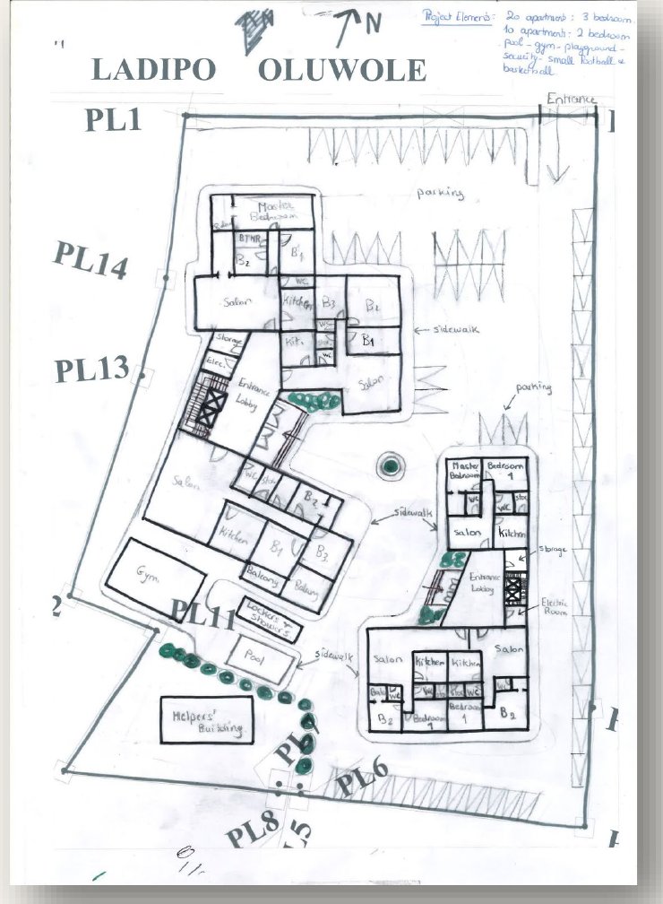
Metal Berg sketch thumbnail
Metal Berg Complex
Apapa · 30-unit staff residences
Palmview sketch thumbnail
Palmview Residence
Private client · indoor-outdoor addition
No drawing loaded yet —
drop a file or load the sample above
02 · Zoning & Program Parameters All fields adjustable
Site & Zoning
m
m
ratio
Program Brief
Three-bedroom units
20
Two-bedroom units
10
Amenities
Lap pool + deck
Gym & lounge
Helpers / drivers annex
Surface parking
Pipeline runtime ≈ 8 seconds
Autonomous Pipeline Running
Compiling schematic proposal
metal-berg-apapa-01.dwg → deterministic render pipeline
0%Initializing…
Metal Berg Staff Residential Complex
Apapa, Lagos · Concept Design Study · Rev A
00 / COVER & SUMMARY

A shared residential
landscape for Metal Berg staff.

Two residential blocks, a common arrival court, and a landscaped amenity cluster — generated from a hand-marked site sketch and resolved against Apapa municipal setback and FAR limits.

30Apartments
20 / 103-BHK / 2-BHK
3,511 m²Site Area
1.82FAR Achieved
G+4Massing
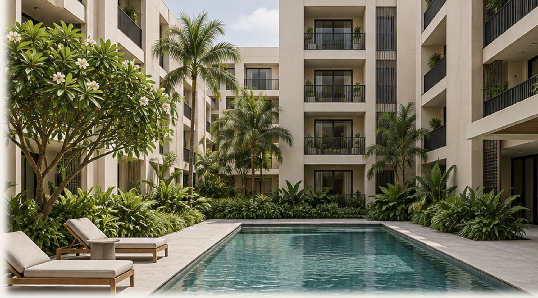
Courtyard atmosphere reference
Atmosphere reference — shaded courtyard, lap poolBoard 04 detail →
01 / CLIENT

The Line — Engineering & Contracting

Reference dataset for this demonstration run. Staff housing brief for the Metal Berg site, Apapa.

02 / INPUT

Single hand-marked sketch

One annotated site sketch, parsed into a vector boundary and a functional room graph.

03 / OUTPUT

7-board proposal deck

Context, plans, units, materials, a feasibility audit and a handoff roadmap — rendered in one pass.

01 / SITE CONTEXT

From hand study to developed plan.

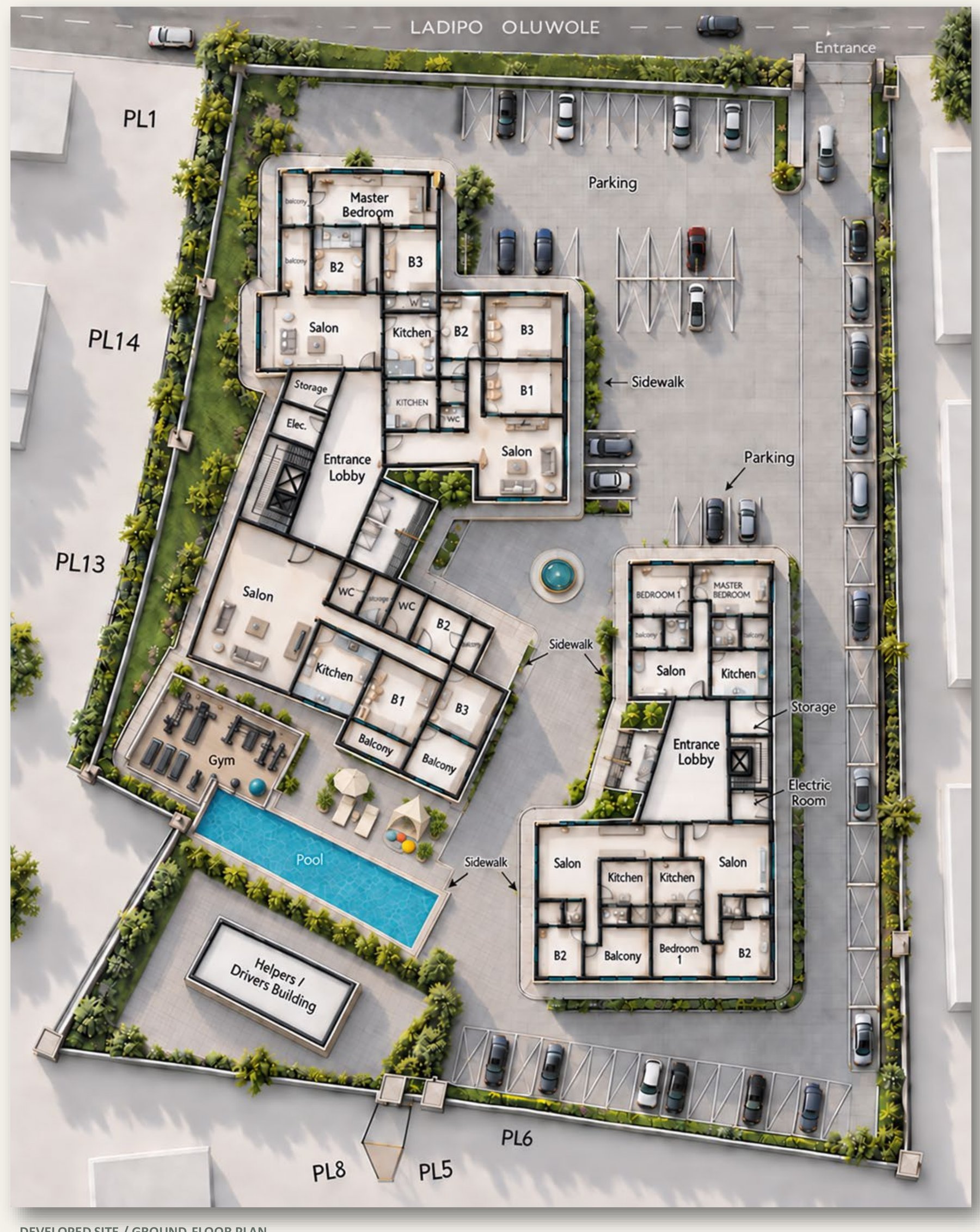
Drag the slider — the engine locks room boundaries and wall positions from the sketch, then textures, furnishes and shades the model without altering the underlying geometry.

Developed 3D axonometric
Original hand sketch
Hand Sketch Developed 3D Axo
Not a measured planning or parking auditOrientation by page position
01 / Arrival

The entrance at Ladipo Oluwole feeds the parking court and the drive along the right-hand boundary.

02 / Buildings

The larger left-hand block and smaller right-hand block address a shared landscaped centre.

03 / Outdoors

Pool, gym and changing rooms create an amenity cluster; sidewalks link the blocks and shared spaces.

30Apartments
20 / 103-BHK / 2-BHK
3,511 m²Site Area
02 / GROUND FLOOR PLAN

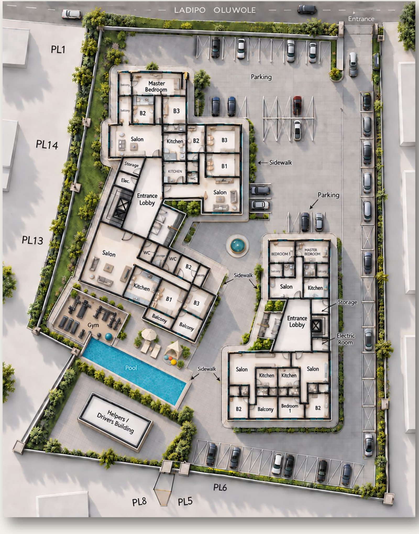
Master ground floor plan.

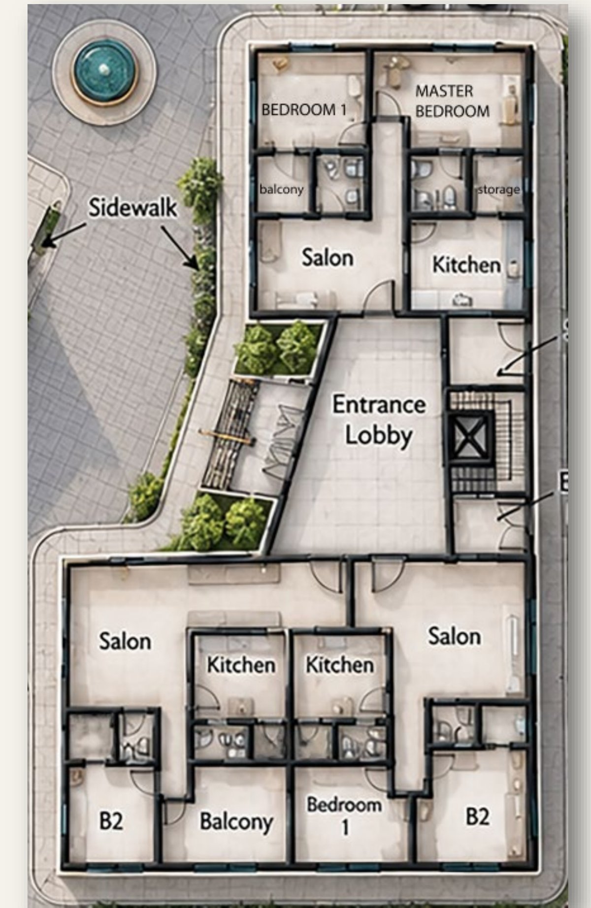
Hover any pin for a callout. The pool sits integrated within the gym building footprint; sidewalks connect both entrance lobbies to the shared amenity court.

Ground floor axonometric with hotspots
A
Block A EntranceLobby & vertical circulation core, larger residential block.
B
Block B Two-BedroomMirror-plan 2BHK units arranged around a shared entrance core.
C
Lap Pool & LoungersPool integrated within the gym building, poolside deck and seating.
D
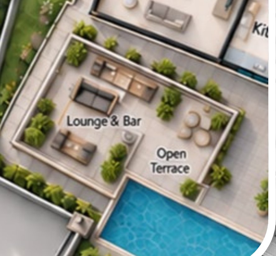
Gym Roof TerraceOpen lounge bar and terrace above the gym pavilion — see inset.

Gym roof — lounge & bar

Zoomed detail above the gym building footprint
Gym roof lounge detail
Circulation

Both blocks share a common lobby and stair/lift arrangement, concentrating arrival and vertical movement.

Services

Nearby wet rooms suggest an opportunity to coordinate plumbing stacks on upper floors.

Develop next

Confirm escape stairs and the floor-by-floor schedule needed to reach the full 20 + 10 apartment brief.

03 / UNIT PLANNING

From the building to the room.

Apartment close-ups, cropped automatically from the master model — public and private zones are separated consistently across both typologies.

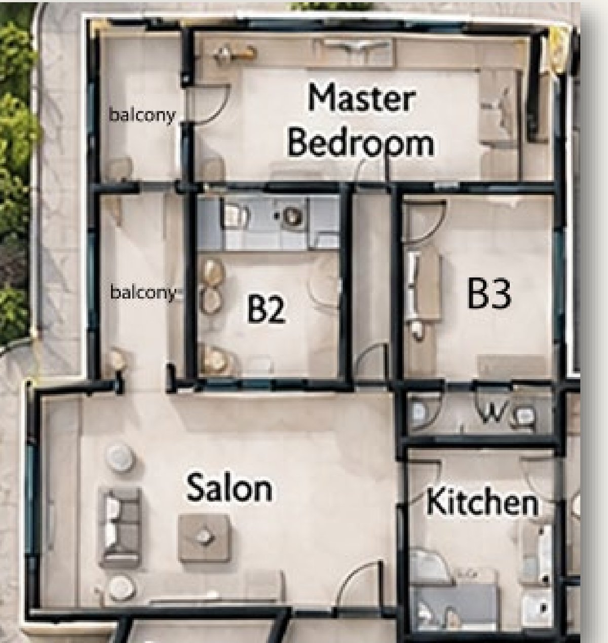
A — Three-Bedroom Family Unit
B — Smaller Residential Block
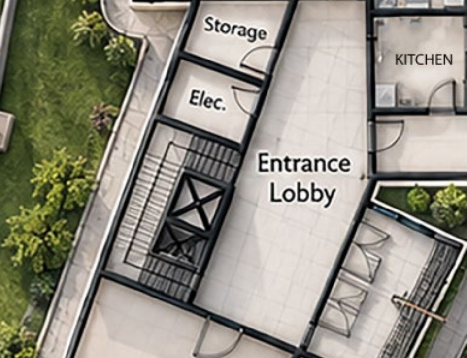
C — Shared Entrance Core
Unit A three-bedroom family unit

Upper apartment, larger block

3
Bedrooms
2
Balconies
1
Salon

The salon sits near the entrance and kitchen. Bedrooms occupy the outer edges, with balcony access shown to selected rooms — B2 and the master suite both open outward.

Unit B smaller residential block

Two-bedroom layouts, shared core

4
Units / floor
1
Shared lobby
2
Kitchens paired

Mirror-plan 2BHK units wrap a shared entrance lobby and stair core, with kitchens paired back-to-back to simplify the plumbing stack above ground level.

Unit C shared entrance core

Larger block — entrance core

1
Lift + stair
2
Service rooms

Lobby, stair/lift symbol and service rooms concentrate arrival and vertical movement, with electrical and storage rooms directly adjacent.

Next design decisions
  • Check furniture clearances and accessible routes
  • Resolve door conflicts and bathroom ventilation against dimensioned drawings
  • Confirm escape stairs and floor-by-floor schedule for the full 30-unit brief
  • Coordinate plumbing stacks across upper floors
04 / ATMOSPHERE & MATERIALS

Materials for everyday living.

A warm, restrained direction for the buildings, interiors and shared outdoor spaces — subject to physical sample approval.

Courtyard exterior atmosphere
Shaded balconies + planted courtyard
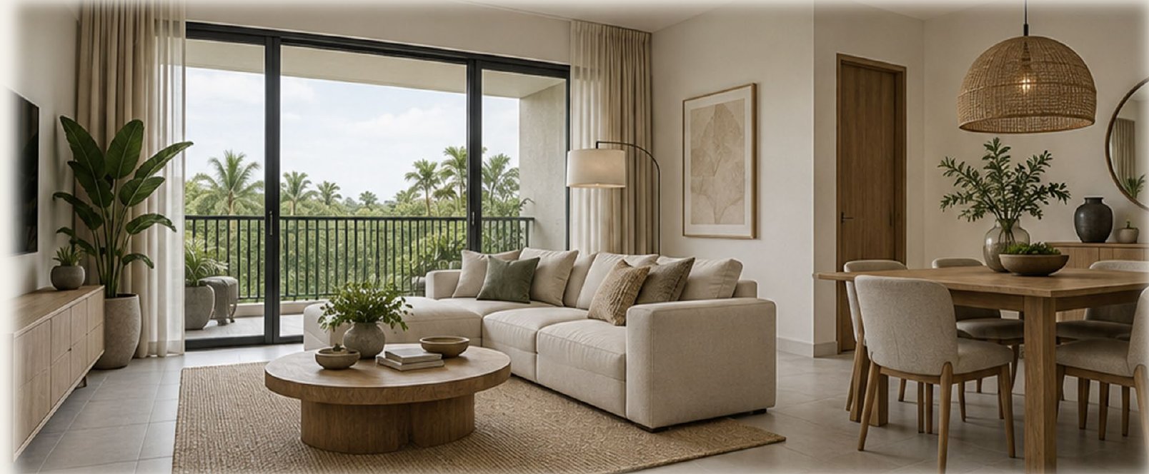
Interior living room atmosphere
Neutral finishes + timber accents

Proposed palette

01
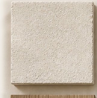
Ivory Render
02
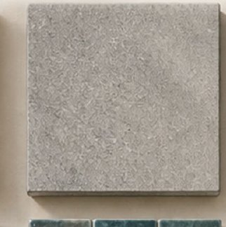
Grey Porcelain
03
Charcoal Frames
04
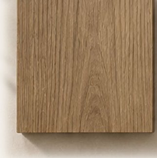
Timber Joinery
05
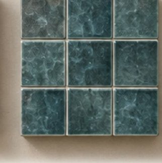
Pool Mosaic
06
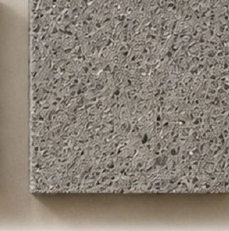
Concrete Paving
Design intention

Shade, privacy and straightforward maintenance guide the façade — warm ivory walls, dark metal frames, recessed balconies.

Shared spaces

Gym, changing rooms and pool pair with a separate helpers' building — develop its sleeping rooms, kitchen and separate male/female bathrooms.

Complete the site brief

Locate the playground, security room, WTP and drainage facilities; coordinate pool safety and plant access.

05 / FEASIBILITY AUDIT

Regulatory & feasibility audit.

The parametric zoning engine insets the site boundary by every setback, checks the drawn massing against the envelope, and totals the resulting unit yield.

FAR / FSI compliance

Achieved floor-area ratio against the Apapa municipal permissible limit
FAR 1.82
Limit 2.20
0.0Permissible: 2.20

Setback audit

Site boundary inset by front and lateral setbacks — no crossings flagged
Property line Front setback 6.0m Lateral 3.5m Lateral 3.5m Buildable envelope

Compliance summary

Automated boolean audit against the drawn massing
Front setback (6.0m)Compliant
Lateral setbacks (3.5m)Compliant
Max height (18.0m / G+4)Compliant
FAR / FSI (1.82 of 2.20)Compliant
Parking provision (35+ stalls)Compliant

Unit yield

30 apartments against the 3,511 m² plot
TypologyCountShare
Three-bedroom
20 · 67%
Two-bedroom
10 · 33%
Parking stalls
35+
06 / NEXT STEPS

From concept to construction set.

This deck is a schematic starting point. The path from here to a permit-ready package follows a short, predictable sequence.

Complete
Concept design study

Site parsing, zoning audit, massing and this presentation deck — generated from the sketch and program brief.

Next
Dimensioned schematic set

Furniture clearances, accessible routes, escape-stair audit and a confirmed floor-by-floor schedule for all 30 units.

Then
MEP & structural coordination

Plumbing stack alignment across upper floors, structural grid confirmation, and site services — playground, security room, WTP, drainage.

Then
Material sample approval

Physical samples for the six-material palette; façade and finish sign-off with the client.

Final
Permit-ready construction package

Full drawing set issued for municipal approval and tender.

Ready for the next stage?

Export this deck as a client-ready PDF, or reopen the configuration panel to re-run the pipeline against a revised brief.

00 / COVER & SUMMARY

A quiet indoor-outdoor
addition for Palmview.

A single-story kitchen, dining and living pavilion opening onto a planted garden, with a rooftop lounge deck above — generated from a hand-marked floor sketch and resolved against the property's setback envelope.

5Zones
38 m²Shown Footprint
820 m²Plot
0.32FAR Achieved
G+1Massing + Roof Deck
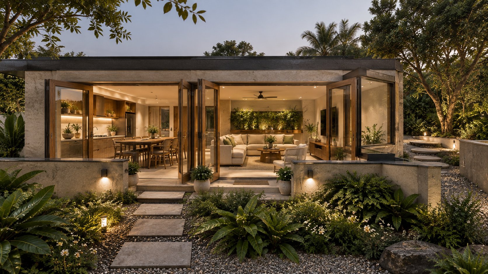
Exterior atmosphere reference at dusk
Atmosphere reference — dusk exterior, indoor-outdoor thresholdBoard 04 detail →
01 / CLIENT

Private Residential Client

Reference dataset for this demonstration run — a single-family addition brief centered on indoor-outdoor living.

02 / INPUT

Single hand-marked floor sketch

One annotated kitchen/living sketch, parsed into a vector boundary and a functional room graph.

03 / OUTPUT

7-board proposal deck

Context, plans, rooms, materials, a feasibility audit and a handoff roadmap — rendered in one pass.

01 / SITE CONTEXT

From hand study to developed plan.

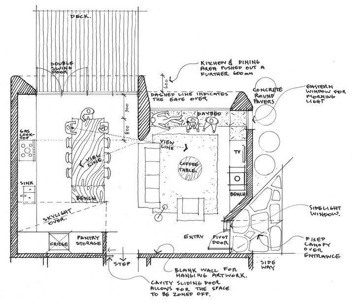
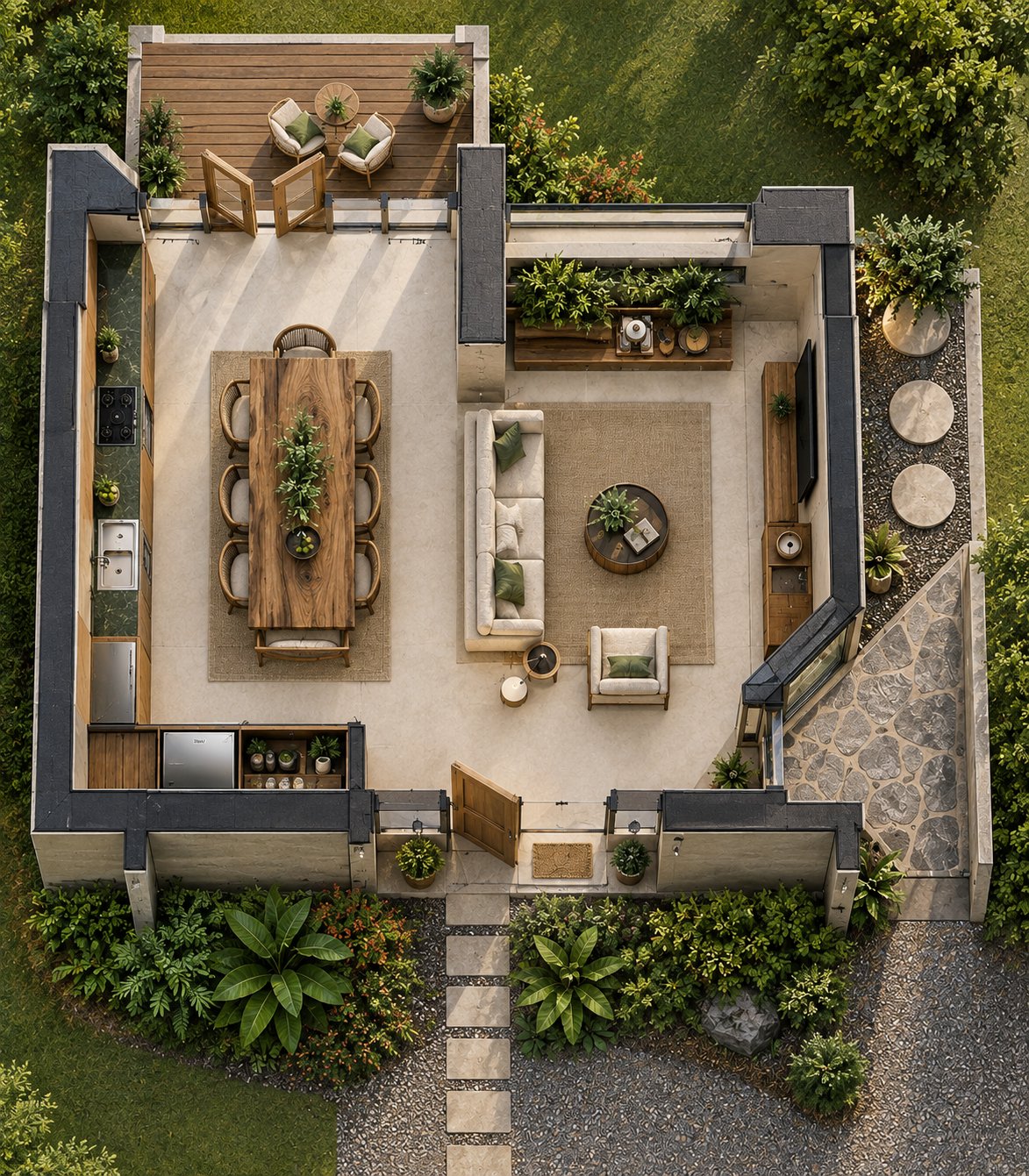
Drag the slider — the same wall geometry from the sketch drives the developed top-down render; nothing is re-proportioned in the process.

Developed top-down render
Original hand sketch
Hand Sketch Developed Top-Down
Not a measured planning auditOrientation by page position
01 / Arrival

A pivot entry door opens directly onto the dining table sightline, with the kitchen run along the left boundary wall.

02 / Layout

A single open-plan pavilion — kitchen, dining and living share one uninterrupted volume, no internal partitions.

03 / Outdoors

A covered deck extends off the living room under a fixed canopy; the garden path steps down through planted beds at the entry.

5Zones
38 m²Shown Footprint
820 m²Plot
02 / GROUND FLOOR PLAN

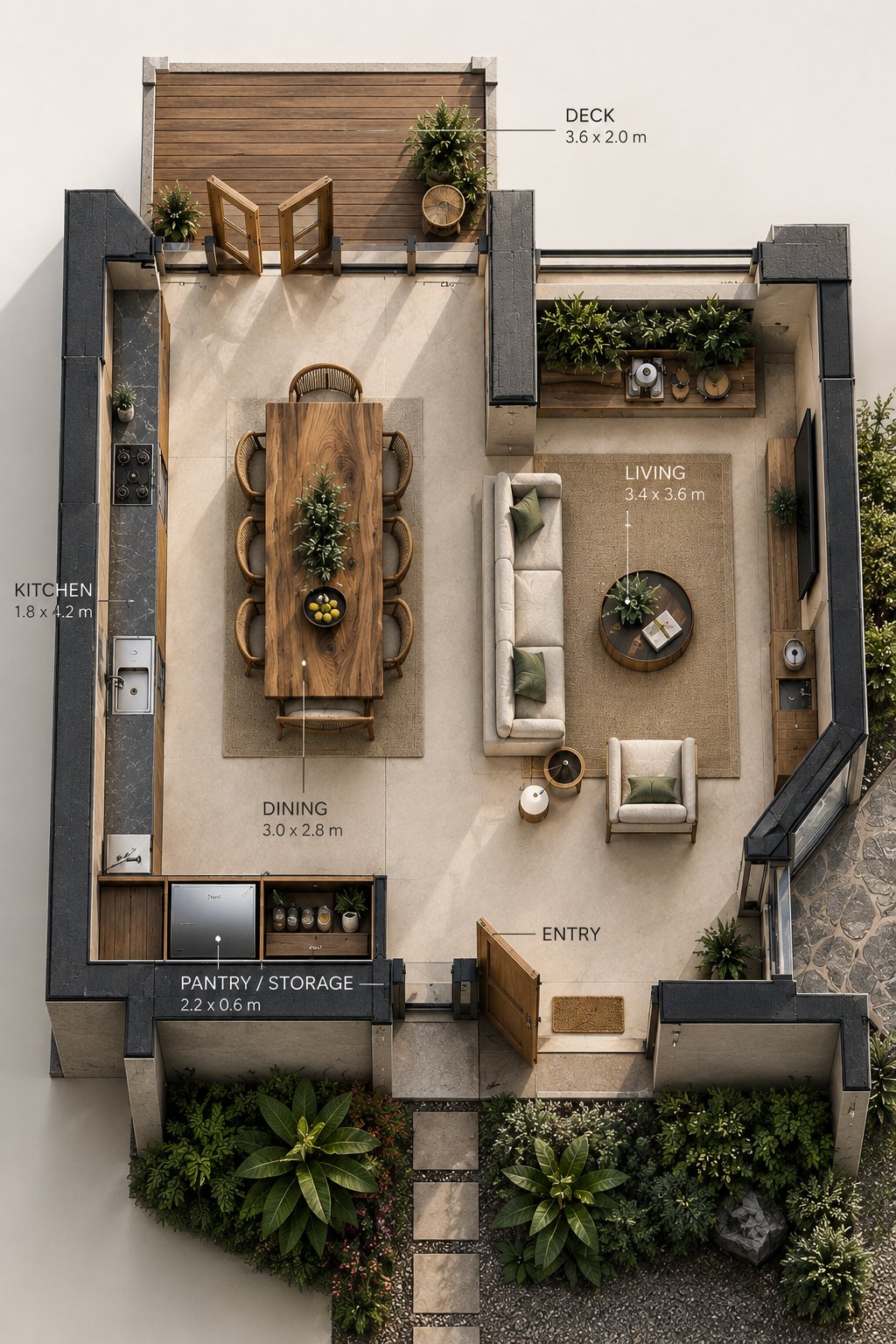
Master ground floor plan.

Hover any pin for a callout. Kitchen, dining and living share one open volume; the deck sits off the living room as a covered outdoor room.

Ground floor plan with hotspots
A
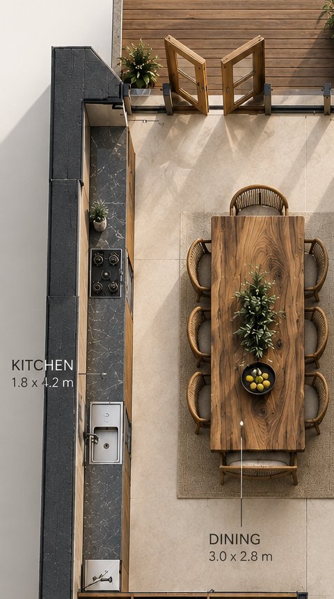
Kitchen RunGas cooktop and sink along the boundary wall, 1.8 × 4.2m.
B
Dining TableCentered on the view line through to the living room, 3.0 × 2.8m.
C
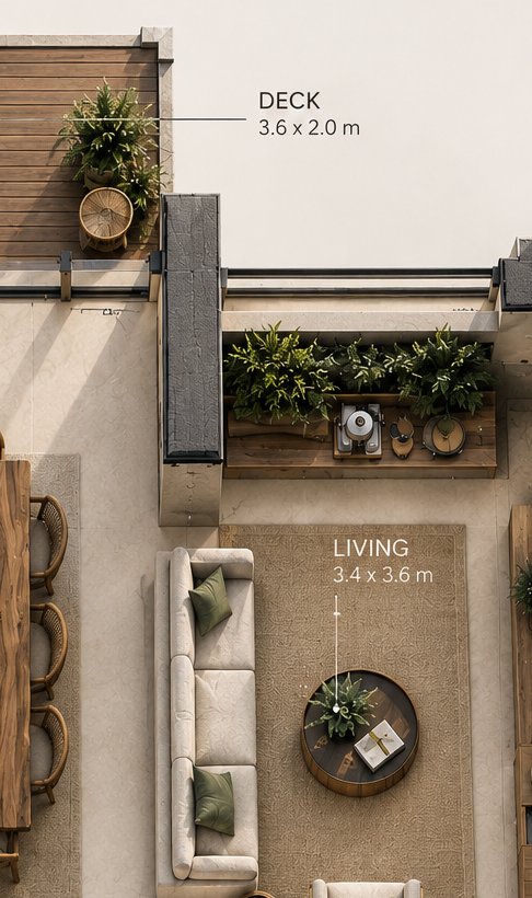
Living + Deck ThresholdWide sliding door opens the living room onto the covered deck.
D
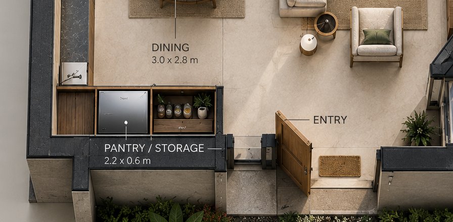
Entry & Pivot DoorPivot entry past a cavity sliding door that can zone the space off.

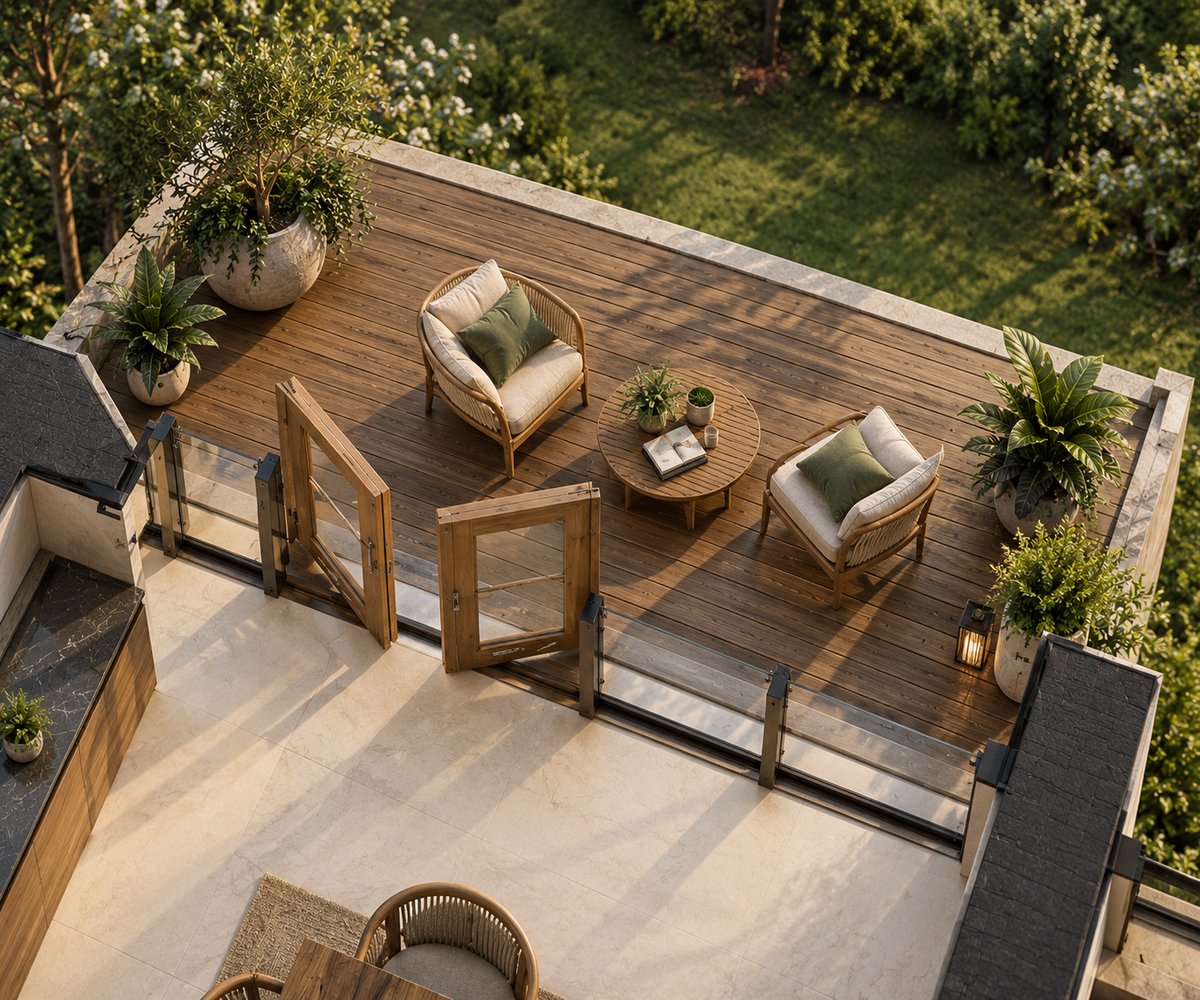
Rooftop lounge deck

Zoomed detail above the main pavilion roofline
Rooftop lounge deck detail
Circulation

A single pivot entry door leads directly into the dining zone, with the kitchen run along the left wall.

Services

The kitchen wet stack — sink and gas cooktop — sits opposite the pantry/storage run for a short service line.

Develop next

Confirm stair or ladder access to the rooftop deck and the structural loading for the terrace above.

03 / ROOM PLANNING

From the building to the room.

Room-group close-ups, cropped automatically from the master model — each carries the sketch's own hand-marked notes through to the developed plan.

A — Kitchen & Dining
B — Living & Deck
C — Entry & Storage
Kitchen and dining room group

Kitchen run & dining table

1.8×4.2m
Kitchen
3.0×2.8m
Dining
1
Shared run

The kitchen runs along the boundary wall with a gas cooktop and sink beneath a skylight; the dining table sits centered on the view line through to the living room.

Living room and deck room group

Living room & covered deck

3.4×3.6m
Living
3.6×2.0m
Deck
1
Sliding threshold

The living room opens directly onto a covered deck through a wide sliding door, with a fixed canopy over the eave carrying the roofline outward.

Entry and pantry room group

Entry, pantry & storage

2.2×0.6m
Pantry
1
Pivot door
1
Sidelight window

A pivot door entry leads past a cavity sliding door that can zone the space off; a fixed canopy and sidelight window bring in morning light at the threshold.

Next design decisions — from the sketch's own notes
  • Confirm the cavity sliding door track and zoning wall thickness
  • Coordinate the kitchen wet-stack venting with the skylight above
  • Detail the fixed canopy structure over the entry sidelight window
  • Confirm rooftop deck access and structural loading above
04 / ATMOSPHERE & MATERIALS

Materials for everyday living.

A warm, restrained direction for the pavilion, interiors and garden threshold — subject to physical sample approval.

Exterior atmosphere at dusk
Dusk exterior, indoor-outdoor threshold
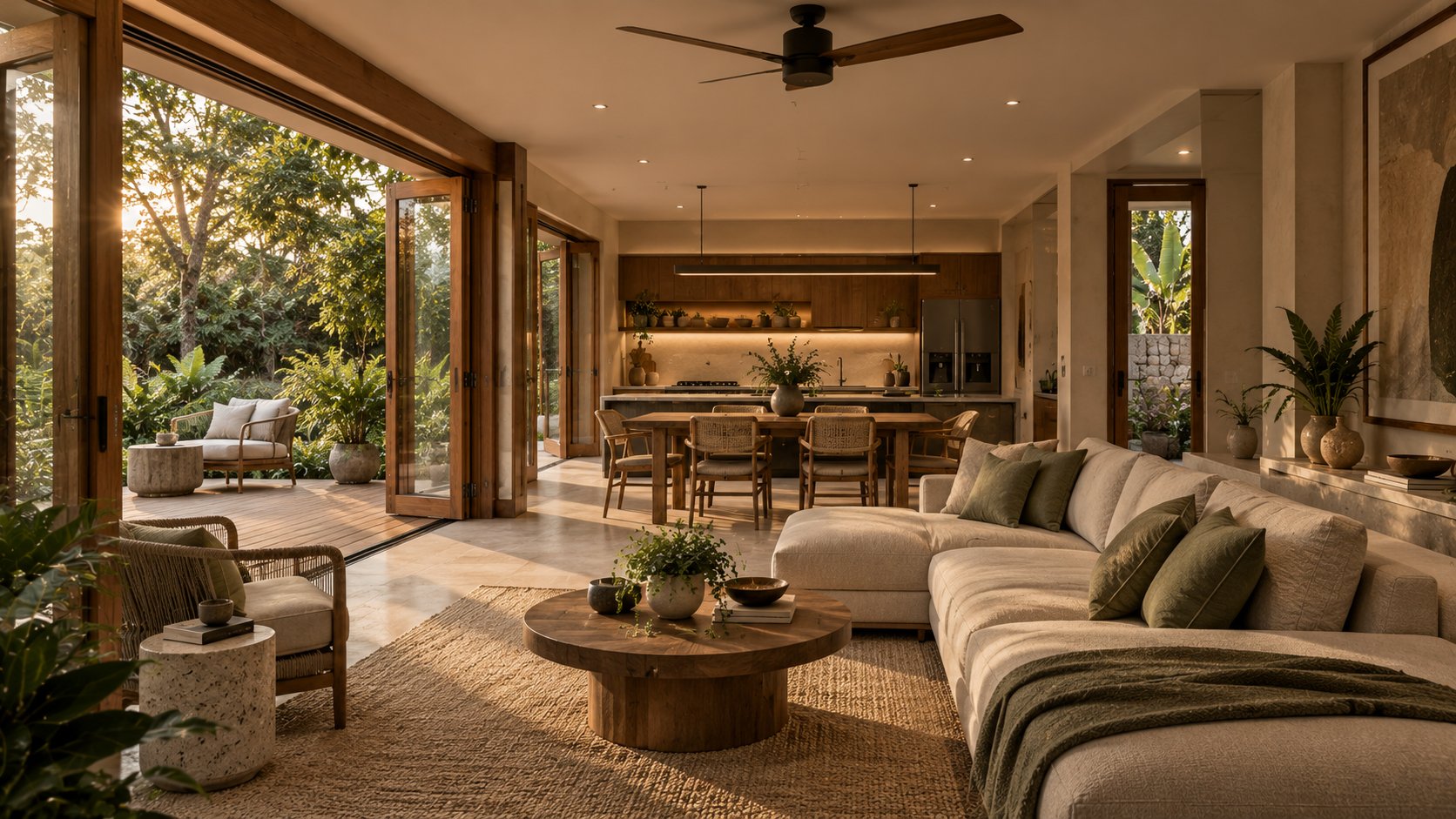
Interior living atmosphere
Neutral finishes + timber accents

Proposed palette

01
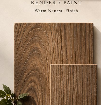
Render / Paint
02
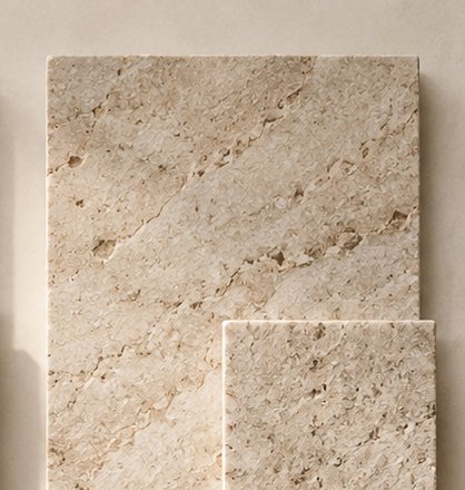
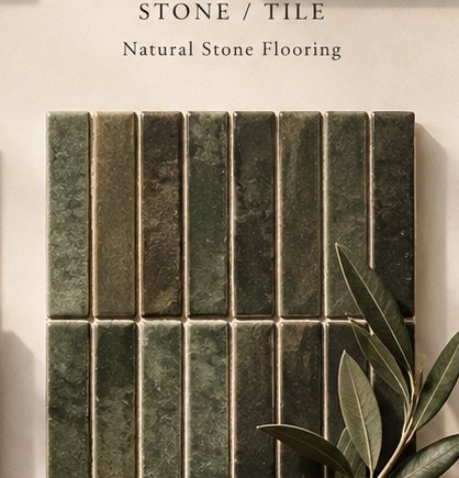
Stone / Tile
03
Metal
04
Timber
05
Mosaic / Accent Tile
06
Paving
Design intention

Warm neutral render, natural stone flooring and brass accents carry from interior to exterior without a hard material break.

Indoor-outdoor threshold

Bi-fold and sliding doors fully retract so the kitchen, dining and living zones read as one volume with the garden.

Complete the brief

Confirm the rooftop deck's planting weight limits, exterior lighting plan and stone paving pattern at the entry path.

05 / FEASIBILITY AUDIT

Regulatory & feasibility audit.

The parametric zoning engine insets the site boundary by every setback, checks the drawn massing against the envelope, and totals the resulting room areas.

FAR / FSI compliance

Achieved floor-area ratio against the permissible limit for this lot
FAR 0.32
Limit 0.65
0.0Permissible: 0.65

Setback audit

Site boundary inset by front and side setbacks — no crossings flagged
Property line Front setback 4.5m Side 2.0m Side 2.0m Buildable envelope

Compliance summary

Automated boolean audit against the drawn massing
Front setback (4.5m)Compliant
Side setbacks (2.0m)Compliant
Max height (6.0m / G+1)Compliant
FAR / FSI (0.32 of 0.65)Compliant
Rooftop deck structural loadPending review

Room area breakdown

38 m² across the five labeled zones shown
ZoneShareArea
Living
12.2 m² · 33%
Dining
8.4 m² · 23%
Kitchen
7.6 m² · 21%
Deck
7.2 m² · 19%
Pantry / Storage
1.3 m² · 4%
06 / NEXT STEPS

From concept to construction set.

This deck is a schematic starting point. The path from here to a permit-ready package follows a short, predictable sequence.

Complete
Concept design study

Site parsing, zoning audit, massing and this presentation deck — generated from the sketch and program brief.

Next
Dimensioned schematic set

Confirm the skylight, cavity door track and canopy structure against dimensioned drawings.

Then
Structural & roof deck coordination

Rooftop terrace loading, waterproofing detail and access route confirmed with the structural engineer.

Then
Material sample approval

Physical samples for the six-material palette; render, stone and timber sign-off with the client.

Final
Permit-ready construction package

Full drawing set issued for municipal approval and tender.

Ready for the next stage?

Export this deck as a client-ready PDF, or reopen the configuration panel to re-run the pipeline against a revised brief.

Compiling client PDF…
Board 1 of 7